Dowel drilling line, unstacker stackerBIESSE COMIL RBO
BIESSE RBO


Machine data
- Machine type:
- Dowel drilling line, unstacker stacker
- Manufacturer:
- BIESSE COMIL RBO
- Model:
- BIESSE RBO
- Condition:
- ready for operation (used)
Price & Location
- Seller location:
- 58000 Nevers, France
Details about the offer
- Listing ID:
- A9321698
- Reference number:
- C2330
- Update:
- 24.09.2024
Description
Single column unloader with suction cups. It is suitable for unloading in machining lines requiring machines with reduced dimensions.
BODY OF THE MACHINE
The machine is composed of a vertical column, a horizontal bracket fixed to the carriage, a carriage fixed to the bracket and a suction cup holder frame unit. The carriage slides on linear guides equipped with ball bearings and is driven by a gear motor controlled by a frequency variator.
SUCTION CUPS PANEL COLLECTION GROUP
It consists of a suction cups row containing 10 suction cups with bellows to facilitate the separation of the panel. Suction cup diameter of 95 mm. The suction cups are operated by a vacuum pump with a flow rate of 22 m3/h.
ELECTRICAL CABINET
The machine is equipped with a separate electrical cabinet, managed by a PLC operating logic.
PROTECTIONS FOR THE PREVENTION OF WORK ACCIDENTS
The machine is protected on all the action perimeter of the suction cups group by protective panels. The battery insertion area is protected by a grid with button opening.
DIMENSIONS OF THE WORKABLE PANELS :
Length: 320 to 2700 mm
Width : 250 to 700 mm
Thickness : 12 to 50 mm
Maximum weight : 50 kg
Pneumatic brake idler roller
LOAD TRANSFER IN SINGLE LONGITUDINAL ROW
Transfer of introduction with inclined rollers to the left, covered in PVC. The rollers are driven by small belts activated by a gear motor under the control of a speed variator. The transfer is also equipped with a left hand guide adjustable by handwheel.
Structure
The structure is made of welded steel, reinforced to ensure maximum stability and precision during the operating phases.
Work surface
The worktop is made up of a transfer in four independent sections.
The first section includes :
An input transfer with flat belts driven by an asynchronous motor controlled by a frequency converter
The second and third sections (drilling planes) each include:
A belt transfer with: flat belts driven by asynchronous motor controlled by frequency converter
A lateral reference guide, installed on the left side of the machine, with lateral stop function Pneumatic end stops for the positioning of right and left panels
A lateral presser guide to guide and clamp panels of different widths against the lateral reference stop.
Bodpfx Aek Rticegkjld
The fourth section includes:
a belt transfer for the evacuation of the panels with :
flat belts driven by asynchronous motor controlled by frequency checker.
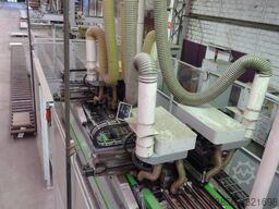
Machining center
The first center consists of a mobile carriage along the X axis on which two independent drilling heads are installed along the Y and Z axes.
Each drilling head is composed as follows:
In the X direction, 10 independent vertical chucks
In the direction of the Y axis, 9 independent vertical mandrels
The second center consists of a mobile carriage along the X axis on which two independent drilling heads are installed along the Y and Z axes.
Each drilling head is composed as follows:
In the X direction, 10 independent vertical chucks
In the Y direction, 9 independent vertical spindles.
Each operating head is suitable for the installation of an additional operating unit to be chosen as an option
Axis movements
Precision linear guides with circulating ball bearings and brushless motors for X,Y,Z axes.
Rectified helical rack coupled to two pinions to allow the recovery of the play along the X axis.
Hardened and ground ball screw (Y,Z axis).
Pneumatic balancing device (Z axis) of the drilling unit.
Numerical control
XNC model bas
Send inquiry


 Siedlce
 CORMAKC1212 PREMIUM 1200x1200


 Vall de Uxó
 Storti


 Miechucino
 StortiRM 500


 München
 Pitney BowesDI425


 Roreto
 WEEKE (HOMAG Group)PROFI BST 800


 Roreto
 IMACombima II/390/B/R3


 Roreto
 IMACombima /II/230/A/R3


 Roreto
 WEEKE (HOMAG Group)BST 500/D


 Bilbao
 ABBIRB 1600iD IRC5 M2004 Multi move


 Roreto
 RBO (BIESSE Group)Tornado SC/FE 1300

Machineseeker Trust Seal
What is the trust seal?
Machineseeker certifies selected sellers with the Machineseeker trust seal. Before approval, a standardized and comprehensive check is carried out by experienced Machineseeker staff.
What do we verify?

Check of
trade licence or commercial register extract
Verification of the dealer's
postal address
Validation of the
banking details
Verification of
accessibility to
main phone number
Credit report
may not contain negative criteria
Buyer complaints
can lead to withdrawal of the sealWhat does this mean for you as buyer?
The Machineseeker trust seal enables you, as a buyer, to identify trustworthy sellers who are very likely to do honest and righteous business, without having to do your own investigation.
Disagreements may of course still arise during the purchasing process. Machineseeker is not liable for any legal violations by buyers or sellers active on Machineseeker.